Tutorial 1: Experimental Parameters
1. Detector Parameters
1.1 PONI File
The pygid.ExpParams class stores the experimental parameters of the detector and the X-ray wavelength. These parameters are needed to calculate the reciprocal-space coordinates of each pixel on the area detector.
The easiest way to load them is using a PONI file, similar to the pyFAI library [https://pyfai.readthedocs.io].
When you create an ExpParams instance, it reads the PONI file from the poni_path you provide. It loads the position of the point of normal incidence (in meters) and the detector rotation angles (in radians). You can create a PONI file from a calibrant image using the pyFAI-calib2 GUI: [https://www.silx.org/doc/pyFAI/latest/usage/cookbook/calib-gui/index.html].
The pixel size is set automatically based on the detector. If your detector is custom or unknown, provide px_size in meters.
Important: Make sure the detector orientation is set to 3. For grazing-incidence experiments, also set the angle of incidence (ai) in degrees.
Before using the detector parameters, download the example files from Zenodo:
from pygid.datasets import get_dataset

# Download example dataset from Zenodo
try:
    files = get_dataset("tutorial_01")
    poni_path = files["poni"]
    mask_path = files["mask"]
except:
    print("Dataset download skipped on Read the Docs.")
Load experimental parameters from PONI:
import pygid
params = pygid.ExpParams(
    poni_path=poni_path,            # path to the PONI file
    ai = 0.01,                       # angle of incidence (in degrees)
)
print(params)
ExpParams(poni_path='/home/docs/.cache/pygid/tutorial_01/LaB6_2024_07_ESRF_ID10.poni', mask_path=None, mask=None, flipud=False, fliplr=False, transp=False, px_size=7.5e-05, img_dim=None, n=None, SDD=0.3271661836504515, wavelength=0.6199209921660013, rot1=-0.0026308680554001304, rot2=-0.004647717026373591, rot3=0.0, poni1=0.1446949272569577, poni2=0.14877525660652482, centerX=None, centerY=None, k=None, count_range=None, ai=0.01, scan=None)
Note: The class is associated with a single geometry; therefore, separate class instances must be created for different PONI files. For incident-angle scans, see Tutorial 7.
1.2 Direct Loading
Instead of using a PONI file, you can also load the detector parameters manually. You need to provide:
Sample-to-detector distance
SDD(in meters)Point of normal incidence
poni1(vertical) andponi2(horizontal) in metersDetector rotation angles
rot1,rot2,rot3(in radians)Pixel size
px_size(in meters)Wavelength
wavelength(in angstroms)Angle of incidence
ai(in degrees)
import pygid

params = pygid.ExpParams(
    SDD=0.327,          # Sample-to-detector distance (m)
    wavelength=0.6199,  # Wavelength (Å)
    rot1=-0.0026,       # Detector rotation X (radians)
    rot2=-0.0046,       # Detector rotation Y (radians)
    rot3=0,             # Detector rotation Z (radians)
    poni1=0.145,        # Beam vertical position (m)
    poni2=0.149,        # Beam horizontal position (m)
    px_size=75e-6,      # Detector pixel size (m)
    ai=0.01             # Angle of incidence (degrees)
)
print(params)
ExpParams(poni_path=None, mask_path=None, mask=None, flipud=False, fliplr=False, transp=False, px_size=7.5e-05, img_dim=None, n=None, SDD=0.327, wavelength=0.6199, rot1=-0.0026, rot2=-0.0046, rot3=0, poni1=0.145, poni2=0.149, centerX=None, centerY=None, k=None, count_range=None, ai=0.01, scan=None)
Instead of poni1 and poni2, you can also provide centerX and centerY in pixels (relative to the bottom-left corner):
import pygid

params = pygid.ExpParams(
    SDD=0.327,          # Sample-to-detector distance (m)
    wavelength=0.6199,  # Wavelength (Å)
    rot1=-0.0026,       # Detector rotation X (radians)
    rot2=-0.0046,       # Detector rotation Y (radians)
    rot3=0,             # Detector rotation Z (radians)
    centerX=1909,       # Beam vertical position (m)
    centerY=1996,       # Beam horizontal position (m)
    px_size=75e-6,      # Detector pixel size (m)
    ai=0.01             # Angle of incidence (degrees)
)
print(params)
ExpParams(poni_path=None, mask_path=None, mask=None, flipud=False, fliplr=False, transp=False, px_size=7.5e-05, img_dim=None, n=None, SDD=0.327, wavelength=0.6199, rot1=-0.0026, rot2=-0.0046, rot3=0, poni1=None, poni2=None, centerX=1909, centerY=1996, k=None, count_range=None, ai=0.01, scan=None)
2. Masking
2.1 Mask from File
You can load a “static” detector mask to remove detector gaps, dead or hot pixels, and the beam stop shadow.
Provide the path to the mask file (mask_path) in any supported format: EDF, TIFF, or NPY.
Pixels with value 1 in the mask will be replaced with numpy.nan.
import pygid
params = pygid.ExpParams(
    poni_path=poni_path,
    mask_path=mask_path,
    ai=0.01
)
print(params.mask.shape)
(2162, 2068)
2.2 Mask as a NumPy Array
If the mask is already loaded as a NumPy array, you can pass it directly to ExpParams:
import pygid
import numpy as np

mask_array = np.load(mask_path) # numpy array with the mask

params = pygid.ExpParams(
    poni_path=poni_path,
    mask=mask_array,
    ai=0.01
)
print(params.mask.shape)
(2162, 2068)
2.3 Dynamic Mask
A “dynamic” mask can be used to mask very strong or very weak reflections that vary from image to image.
To use it, provide count_range as a tuple (min, max) defining the intensity range.
The dynamic mask can be used together with or instead of the static mask:
import pygid

params = pygid.ExpParams(
    poni_path=poni_path,
    mask_path=mask_path,
    count_range=(10, 10000),  # intensity range for dynamic masking
    ai=0.01
)
3. Image Flipping & Transposition
In some cases, the detector image must be flipped or transposed prior to conversion. The following boolean parameters control these operations:
fliplr = True— horizontal flipping (left-to-right)flipud = True— vertical flipping (upside-down)transp = True— transposition (swap of X and Y axes) — can be used when the detector was rotated
These operations modify the detector orientation and therefore alter the corresponding experimental geometry:
point of normal incidence:
if transp:
    poni1, poni2 = poni2, poni1
if flipud:
    poni1 = img_dim[0] * px_size - poni1
if self.fliplr:
    poni2 = (img_dim[1] - 1) * px_size - poni2
where img_dim - image dimensions; px_size - pixel size
detector rotation angles:
if transp:
    rot1, rot2 = -rot2, -rot1
if flipud:
    rot2 = -rot2
    rot3 = -rot3
if fliplr:
    rot1 = -rot1
    rot3 = -rot3
The effect of these options on the conversion result is illustrated below:
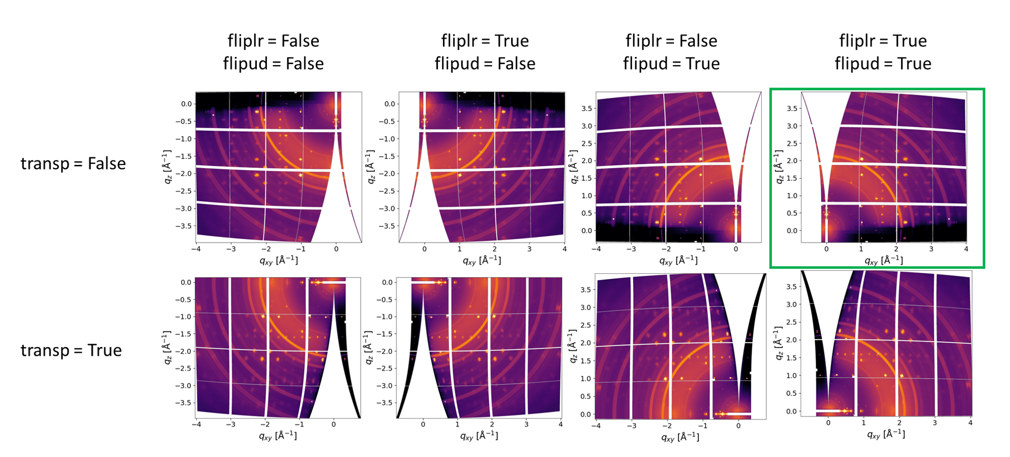
The correct combination is highlighted in green.
In particular cases, when rot3 (rotation around the beam) in non-zero, rot3 changes the sign when flipud or fliplr are used.
Note:
rot3 ≠ 0andtransp = Trueshould not be used simultaneously, as this leads to an ambiguous detector orientation.
After loading the experimental parameters, you can calculate the coordinate maps. This is covered in Tutorial 2.